I want to be able to offer both 4:3 modes and 16:9 mode (since most TVs are widescreen now). So I did up a little spreadsheet that computes the Video RAM and pixel clock requirements given that I want the following features:
- Double buffering (2 frame buffers in VRAM with page flipping).
- Clear entire screen at 60 fps.
- 8 bits per pixel (3 bits Red, 3 bits Green and 2 bits Blue)
Having 8 bits per pixel arranged in this way yields a palette like this:
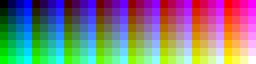
This should look pretty tasty indeed. Here is the spreadsheet:
| width | height | bytes/ page | rounded page | bytes total | SRAM Chip | total waste | A pins/ page | total pins | Pixel Clock | Mode | ||
| 104 | 78 | 8,112 | 8,192 | 16,384 | (16K x 8) | 160 | 13 | 23 | 486,720 | 104 x 78 | 4:3 resolutions | |
| 144 | 108 | 15,552 | 16,384 | 32,768 | (32K x 8) | 1,664 | 14 | 24 | 933,120 | 144 x 108 | ||
| 208 | 156 | 32,448 | 32,768 | 65,536 | (64K x 8) | 640 | 15 | 25 | 1,946,880 | 208 x 156 | ||
| 288 | 216 | 62,208 | 65,536 | 131,072 | (128K x 8) | 6,656 | 16 | 26 | 3,732,480 | 288 x 216 | ||
| 320 | 240 | 76,800 | 131,072 | 262,144 | (256K x 8) | 108,544 | 17 | 27 | 4,608,000 | 320 x 240 | ||
| 360 | 270 | 97,200 | 131,072 | 262,144 | (256K x 8) | 67,744 | 17 | 27 | 5,832,000 | 360 x 270 | 1080 mode | |
| 416 | 312 | 129,792 | 131,072 | 262,144 | (256K x 8) | 2,560 | 17 | 27 | 7,787,520 | 416 x 312 | ||
| 480 | 360 | 172,800 | 262,144 | 524,288 | (512K x 8) | 178,688 | 18 | 28 | 10,368,000 | 480 x 360 | 720 mode | |
| 512 | 384 | 196,608 | 262,144 | 524,288 | (512K x 8) | 131,072 | 18 | 28 | 11,796,480 | 512 x 384 | 768 mode | |
| 584 | 438 | 255,792 | 262,144 | 524,288 | (512K x 8) | 12,704 | 18 | 28 | 15,347,520 | 584 x 438 | ||
| 720 | 540 | 388,800 | 524,288 | 1,048,576 | (1024K x 8) | 270,976 | 19 | 29 | 23,328,000 | 720 x 540 | 1080 mode | |
| 160 | 90 | 14,400 | 16,384 | 32,768 | (32K x 8) | 3,968 | 14 | 24 | 864,000 | 160 x 90 | 16:9 resolutions | |
| 224 | 126 | 28,224 | 32,768 | 65,536 | (64K x 8) | 9,088 | 15 | 25 | 1,693,440 | 224 x 126 | ||
| 320 | 180 | 57,600 | 65,536 | 131,072 | (128K x 8) | 15,872 | 16 | 26 | 3,456,000 | 320 x 180 | ||
| 480 | 270 | 129,600 | 131,072 | 262,144 | (256K x 8) | 2,944 | 17 | 27 | 7,776,000 | 480 x 270 | 1080 mode | |
| 640 | 360 | 230,400 | 262,144 | 524,288 | (512K x 8) | 63,488 | 18 | 28 | 13,824,000 | 640 x 360 | 720 mode | |
| 960 | 540 | 518,400 | 524,288 | 1,048,576 | (1024K x 8) | 11,776 | 19 | 29 | 31,104,000 | 960 x 540 | 1080 mode |
I have computed the number of GPIO pins required to address one page of the framebuffer. For example, a video mode of 480x270 (Widescreen) consumes 230,400 bytes per page. Rounding up to the nearest power of 2 and multiplying by 2 (for 2 pages) requires a 512 KByte VRAM. In order to clear the screen at 60 fps, I need to be able to write 7,776,00 bytes per second. Now that is a lot of bandwidth for a 20Mhz 8-bit AVR.
Can it be done? Well, at that resolution I would need 17 address pins per page + 8 pins for the data + 1 pin for SRAM Write/Enable + 1 pin for the page select. So I'd need 27 GPIO pins in total. That rules out the ATMega328 (Arduino). An ATMega164A might to the trick (digikey.com.au) as it has 32 GPIO pins. So I have enough pins but can I write to the memory fast enough to clear the screen?
In order to test this I dug out my trust Arduino and ran some tests. Here is some sample code:
| void loop() { time = millis(); addr = 0; do { PORTC = (byte)(addr); PORTC = (byte)(addr>>8); PORTC = (byte)(addr>>16); addr++; } while (addr < 7776000); time = millis() - time; Serial.print("Time: "); Serial.println(time); } |
This is supposed to simulate walking through a 18bit address space (17bits per page + page select). The idea is that this is basically what is required to clear a 480x270 area of an SRAM chip 60 times. This runs in 11.2 seconds. Now the chip is running at 16Mhz in this case, so on a 20Mhz setup the time would be more like 8.9 seconds but I'll stick to 16Mhz for now.
11.2 seconds is far too slow. This needs to be less that 1 second in order to meet the constraint I set and ideally much less in order to allow some time to draw some other shapes! There are some things I can do here. I could unroll the loop a bit. Given that I'm clearing the screen to one colour I can safely unroll it as much as I like. This is speed/space trade-off though. Unrolling a loop uses more Flash but my whole Arduino sketch is on 2990 bytes right now and the target chip has 16Kbytes of Flash so I'm pretty safe. This is what the code looks like if I unroll the loop by a factor of 8:
void loop() { time = millis(); addr = 0; do { PORTC = (byte)(addr); PORTC = (byte)(addr>>8); PORTC = (byte)(addr>>16); addr++; PORTC = (byte)(addr); PORTC = (byte)(addr>>8); PORTC = (byte)(addr>>16); addr++; PORTC = (byte)(addr); PORTC = (byte)(addr>>8); PORTC = (byte)(addr>>16); addr++; PORTC = (byte)(addr); PORTC = (byte)(addr>>8); PORTC = (byte)(addr>>16); addr++; PORTC = (byte)(addr); PORTC = (byte)(addr>>8); PORTC = (byte)(addr>>16); addr++; PORTC = (byte)(addr); PORTC = (byte)(addr>>8); PORTC = (byte)(addr>>16); addr++; PORTC = (byte)(addr); PORTC = (byte)(addr>>8); PORTC = (byte)(addr>>16); addr++; PORTC = (byte)(addr); PORTC = (byte)(addr>>8); PORTC = (byte)(addr>>16); addr++; } while (addr < 7776000/8); time = millis() - time; Serial.print("Time: "); Serial.println(time); } | 40: sts 0x0000, r24 44: sts 0x0000, r25 48: ldi r18, 0x00 4a: ldi r19, 0x00 4c: ldi r20, 0x00 4e: ldi r21, 0x00 50: ldi r24, 0x01 52: ldi r25, 0x00 54: ldi r26, 0x00 56: ldi r27, 0x00 58: std Y+9, r24 5a: std Y+10, r25 5c: std Y+11, r26 5e: std Y+12, r27 60: ldi r24, 0x02 62: ldi r25, 0x00 64: ldi r26, 0x00 66: ldi r27, 0x00 68: std Y+5, r24 6a: std Y+6, r25 6c: std Y+7, r26 6e: std Y+8, r27 70: ldi r24, 0x03 72: ldi r25, 0x00 74: ldi r26, 0x00 76: ldi r27, 0x00 78: std Y+1, r24 7a: std Y+2, r25 7c: std Y+3, r26 7e: std Y+4, r27 80: ldi r16, 0x04 82: mov r2, r16 84: mov r3, r1 86: mov r4, r1 88: mov r5, r1 8a: ldi r17, 0x05 8c: mov r6, r17 8e: mov r7, r1 90: mov r8, r1 92: mov r9, r1 94: ldi r27, 0x06 96: mov r10, r27 98: mov r11, r1 9a: mov r12, r1 9c: mov r13, r1 9e: ldi r26, 0x07 a0: mov r14, r26 a2: mov r15, r1 a4: mov r16, r1 a6: mov r17, r1 a8: out 0x08, r18 aa: eor r27, r27 ac: mov r26, r21 ae: mov r25, r20 b0: mov r24, r19 b2: out 0x08, r24 b4: movw r24, r20 b6: eor r26, r26 b8: eor r27, r27 ba: out 0x08, r24 bc: ldd r25, Y+9 be: out 0x08, r25 c0: ldd r24, Y+9 c2: ldd r25, Y+10 c4: ldd r26, Y+11 c6: ldd r27, Y+12 c8: mov r24, r25 ca: mov r25, r26 cc: mov r26, r27 ce: eor r27, r27 d0: out 0x08, r24 d2: ldd r24, Y+9 d4: ldd r25, Y+10 d6: ldd r26, Y+11 d8: ldd r27, Y+12 da: movw r24, r26 | dc: eor r26, r26 de: eor r27, r27 e0: out 0x08, r24 e2: ldd r25, Y+5 e4: out 0x08, r25 e6: ldd r24, Y+5 e8: ldd r25, Y+6 ea: ldd r26, Y+7 ec: ldd r27, Y+8 ee: mov r24, r25 f0: mov r25, r26 f2: mov r26, r27 f4: eor r27, r27 f6: out 0x08, r24 f8: ldd r24, Y+5 fa: ldd r25, Y+6 fc: ldd r26, Y+7 fe: ldd r27, Y+8 100: movw r24, r26 102: eor r26, r26 104: eor r27, r27 106: out 0x08, r24 108: ldd r25, Y+1 10a: out 0x08, r25 10c: ldd r24, Y+1 10e: ldd r25, Y+2 110: ldd r26, Y+3 112: ldd r27, Y+4 114: mov r24, r25 116: mov r25, r26 118: mov r26, r27 11a: eor r27, r27 11c: out 0x08, r24 11e: ldd r24, Y+1 120: ldd r25, Y+2 122: ldd r26, Y+3 124: ldd r27, Y+4 126: movw r24, r26 128: eor r26, r26 12a: eor r27, r27 12c: std Y+13, r24 12e: std Y+14, r25 130: std Y+15, r26 132: std Y+16, r27 134: out 0x08, r24 136: out 0x08, r2 138: eor r27, r27 13a: mov r26, r5 13c: mov r25, r4 13e: mov r24, r3 140: out 0x08, r24 142: movw r24, r4 144: eor r26, r26 146: eor r27, r27 148: out 0x08, r24 14a: out 0x08, r6 14c: eor r27, r27 14e: mov r26, r9 150: mov r25, r8 152: mov r24, r7 154: out 0x08, r24 156: movw r24, r8 158: eor r26, r26 15a: eor r27, r27 15c: out 0x08, r24 15e: out 0x08, r10 160: eor r27, r27 162: mov r26, r13 164: mov r25, r12 166: mov r24, r11 168: out 0x08, r24 16a: movw r24, r12 16c: eor r26, r26 16e: eor r27, r27 170: out 0x08, r24 172: out 0x08, r14 | 174: eor r27, r27 176: mov r26, r17 178: mov r25, r16 17a: mov r24, r15 17c: out 0x08, r24 17e: movw r24, r16 180: eor r26, r26 182: eor r27, r27 184: out 0x08, r24 186: subi r18, 0xF8 188: sbci r19, 0xFF 18a: sbci r20, 0xFF 18c: sbci r21, 0xFF 18e: ldd r24, Y+9 190: ldd r25, Y+10 192: ldd r26, Y+11 194: ldd r27, Y+12 196: adiw r24, 0x08 198: adc r26, r1 19a: adc r27, r1 19c: std Y+9, r24 19e: std Y+10, r25 1a0: std Y+11, r26 1a2: std Y+12, r27 1a4: ldd r24, Y+5 1a6: ldd r25, Y+6 1a8: ldd r26, Y+7 1aa: ldd r27, Y+8 1ac: adiw r24, 0x08 1ae: adc r26, r1 1b0: adc r27, r1 1b2: std Y+5, r24 1b4: std Y+6, r25 1b6: std Y+7, r26 1b8: std Y+8, r27 1ba: ldd r24, Y+1 1bc: ldd r25, Y+2 1be: ldd r26, Y+3 1c0: ldd r27, Y+4 1c2: adiw r24, 0x08 1c4: adc r26, r1 1c6: adc r27, r1 1c8: std Y+1, r24 1ca: std Y+2, r25 1cc: std Y+3, r26 1ce: std Y+4, r27 1d0: ldi r24, 0x08 1d2: ldi r25, 0x00 1d4: ldi r26, 0x00 1d6: ldi r27, 0x00 1d8: add r2, r24 1da: adc r3, r25 1dc: adc r4, r26 1de: adc r5, r27 1e0: add r6, r24 1e2: adc r7, r25 1e4: adc r8, r26 1e6: adc r9, r27 1e8: add r10, r24 1ea: adc r11, r25 1ec: adc r12, r26 1ee: adc r13, r27 1f0: add r14, r24 1f2: adc r15, r25 1f4: adc r16, r26 1f6: adc r17, r27 1f8: cpi r18, 0xE0 1fa: ldi r25, 0xD4 1fc: cpc r19, r25 1fe: ldi r25, 0x0E 200: cpc r20, r25 202: ldi r25, 0x00 204: cpc r21, r25 206: brcc .+0 208: rjmp .+0 |
The loop time is now 1.8 seconds. Wow. That really helped. I have included the assembly output where you can see the effect of the unrolling. This assembly covers the do() loop only. Unrolling to 16 pixels per loop yields 545 milliseconds. Now we are in business.
I need to check these calculations. I seems unreal that an 8-bit micro can write 7.7 million bytes in 0.5 seconds. That is a bandwidth of 15.4 MiBytes/second on a 16Mhz part. Something must be wrong. I have certainly made a mistake somewhere...